Categories Guides How To Post navigation. Horizontal vertical flat and overhead.
The Basics Of Surface Finish Gd T Basics
Engineering drawings could be readily doubled or halved in size.
. When I placed the toposurface I was careful to place it at 150mm below the finished floor level of the warehouse. They are shown enclosed in a box and are the basis for many GDT callouts. Creating Shop Drawings.
Datums are theoretically exact points axes lines and planes or a combination thereof that are derived from datum features. It is important to know that there is no Standard Format and the look and feel can vary greatly from one Draftsman to the next. You can think of them as anchors for the entire part.
Check Out the Beginners Guide. Onshapes CAD drawings can be annotated to comply with ANSI and ISO drawing standards. Profile of a surface is the 3D version of profile of a line.
Our Beginners Guide to Blueprint Reading for more in depth information related to understanding your blueprints and drawings. Sizes of drawings typically comply with either of two different standards ISO World Standard or ANSIASME Y141 American. With the initial project questions issued in the form of an RFI we can now begin working on our Shop Drawings.
My revision clouds after finishing the edit and clicking the big green tick disappear. A datum feature is the tangible surface or feature of size comprised of multiple surfaces or revolved surfaces that is indicated by the datum feature symbol. Add dimensions ordinate dimensions hole callouts datums geometric tolerances weld and surface finish symbols notes tables images and balloon callouts.
This shows up in the right spot when lookin at the building and surrounding area in 3D and when looking in plan view at say the roof apex height around 12m from ground level but on other certain levels like the second floor level the topo disappears. The metric drawing sizes correspond to international paper sizesThese developed further refinements in the second half of the twentieth century when photocopying became cheap. Generally welding positions are the angles at which metals are joined.
If a simple surface is called out such as a radius on a corner a height gauge can be used to trace the part as long as the gauge can stay the same distance away from the surface as rotates around the surface. The revion number and note is added to the bottom of the sheet but no revision cloud. Relation to Other GDT Symbols.
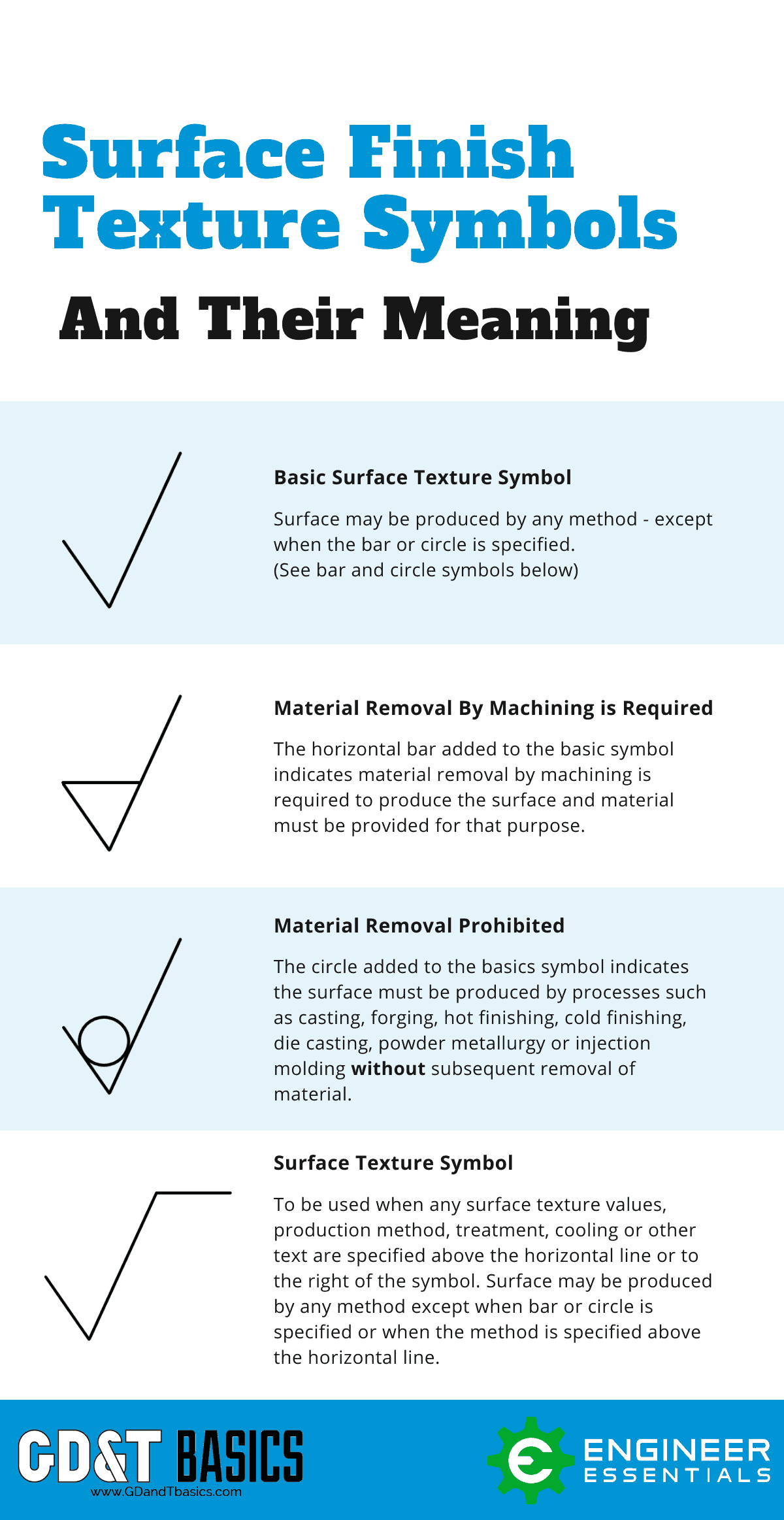
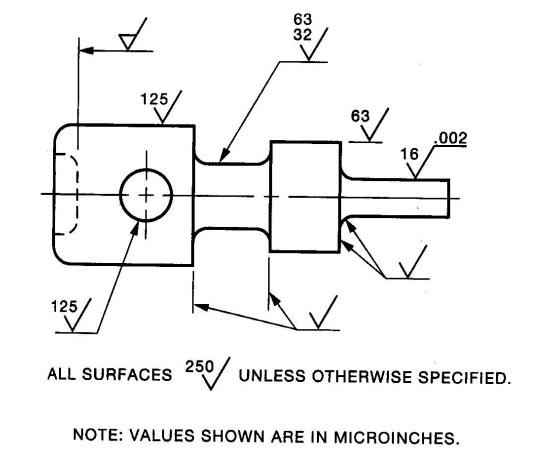
A symbol for defining the surface finish of a part. Engineering drawing abbreviations and symbols are used to communicate and detail the characteristics of an engineering drawingThis list includes abbreviations common to the vocabulary of people who work with engineering drawings in the manufacture and inspection of parts and assemblies. A new phenomenon today after updating R14 yesterday with the rvt2014ur11 patch though this might not be connected.
They usually fall into four categories. Develops the only product design platform that combines 3D CAD PDM collaboration and analytics tools in the cloud.
Complete Surface Finish Chart Symbols Roughness Conversion Tables
Surface Finish Surface Roughness It S Indications Symbols
Surface Roughness Indication Symbols Surface Roughness Symbol Indication In Hindi Youtube

Surface Roughness Symbol In Drawings Mechanical Engineering General Discussion Eng Tips
Complete Surface Finish Chart Symbols Roughness Conversion Tables
Dimensions Surface Finish Roy Mech
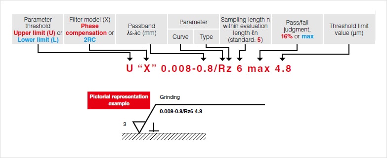
Understanding Surface Roughness Symbols Introduction To Roughness Keyence America
Iso Surface Roughness Symbols Terminology
0 comments
Post a Comment